Sunday, August 19, 2018

Tunneling Under the Mountain... Part 2

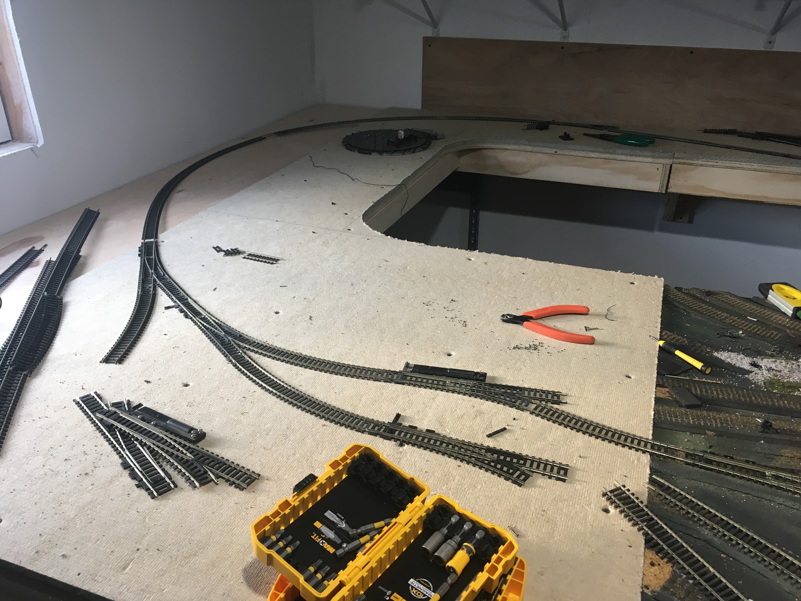
The last step before attaching the spline to the benchwork was to lay the new cork roadbed down.  It was much easier to do so with the spline sitting on the floor next to the layout.  Once the glue dry, the spline was attached to the benchwork and the track was laid.  Fortunately, two pieces of flextrack was sufficient to cover the distance required.  To reduce work over the long reach back to the track, I soldered a set of feewders prior to installation.  I attached the feeders directly to the junction point between the two sections of track, thereby effectively soldering the rails together and ensuring 100% electrical relability for both sections.  


 Here, you can see the track installed and connected to the rest of the layout.  You can clearly see where the old second track was laid, I will clean up the ballast and scenic over it to disguse that it once was there at some point.


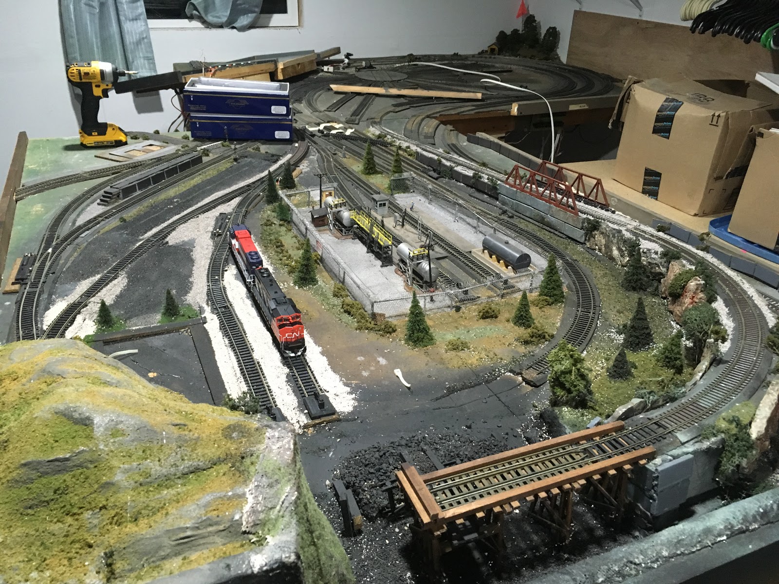
Here is the view under the mountain with the track installed.  The box structure supporting the track in the foreground is part of the assembly for the staging connection.  The staging yard will be discussed further soon.

Monday, August 13, 2018

Tunneling Under the Mountain... Part 1

So with the yard laid, the peninsula connected, and wiring upgraded, I next turned my attention to the far end of the layout.  The photo below shows what was there prior to moving.


Running up the back of the layout, it appears to be a double mainline, however, once exiting from the mountain, it actually ended in an industry siding for the inner track while the outer track continued to the other side of the layout.  The idea of having a switching lead through the tunnel seemed very silly to me.  Also, with 18" and 22" radius respectively, there was concern with operation.  Finally, since I wanted this end of the layout to be the traffic source for the whole layout, I needed a way to incorporate some form of staging.


So, as a common trend with this layout, out came the track.


Removing the track from under the mountain was a challenge.  The mainline had been built on Woodland Scenics risers, so those needed to be removed as well.  A large access hole was cut on the side which gained the necessary access.  While removing the track, I found an old Bachmann gandy dancer hidden away behind the roadbed.  Somehow it had been lost, and survived the move within the mountain.  A neat find.


To build the new line through the mountain, I utilized a spline roadbed section salvaged from an old layout.


To set the hight of the spline to match the rest of the layout, I built a handful of risers.  I used a "L" shape riser to ensure stability and to give me a bit more material to bite into when attaching the risers to the layout.


And finally,  the road bed in place.  A little clean up and and I'll be ready to lay roadbed and track, but that will be for another post.

Monday, August 6, 2018

Juicing the Layout

One of the first things I noticed with this layout when I got it, was the generally poor condition of the layout wiring.  Substandard wiring, reliance on rail joiner feeders in totally inadequate quanities, and haphazard design, all led to the quick decision, it would be best to start again from scratch.

So I tapped into the wire supply I had on hand for my Somerset project.  12 gage buss wire and 20 gage feeders would once again be standard.  One very important factor to keep in mind is correctly color coding the buss and feeders.  I had white and black wire on hand.  White was designated for the rail closest to the edge of the benchwork, black closer to the back.

Installing a feeder in the yard. 

Typical feeder bundle connected to the buss. 

 Another view.
 
The secondhand layout came with a few Miniatronics boards shown above.  Typically I prefer soldered connections over mechanical connections, but since these were on hand, I decided to give them a try.  My opinion is that they worked out well, but I'd have a hard time justifying the expense in the future, over the essentially free option of soldering the connections.

Sunday, July 29, 2018

Connecting the Peninsula

One of the first tasks after installing the new corner section was to lay the track connecting the peninsula to what will be the yard.  I actually laid the connecting track first, before laying the yard, so the last post was jumping the gun a little bit.

 This was the initial attempt.  Notice the lack of homasote at the back.  This would be filled in later.  One great advantage to homasote is that you can easily make changes to the design.  I was not happy with this attempt, I wanted to maximize the length of the run around track, and I did not like the flow into the industry sidings.

 Take two.  By relaying the switches I was able to gain another car length in the siding.  Also the flow is much better.  The missing piece of homasote is now installed.  The siding to the left will be used for a small industry, and is positioned to allow for future expansion down that wall as well.

A view from the other side of the peninsula.  The switch to nothing is intended to access the ramp to the coal dump.  I have not decided if I like this industry or not.
A view from the end of the peninsula.  I've tossed a few buildings around on the layout, but nothing is for sure yet.

Sunday, July 22, 2018

Oh Look, A Yard...

As I alluded to in my previous post, I've also been able to get the connecting section built, and began laying out what will become the primary yard for the layout.  Trains will arrive here from staging.  A switcher will break the train down, and set up the locals originating out of the yard, both east to the peninsula, and west to Dragon Cement.  Because of the peninsula, I was limited for space.  There is approximately four feet between the peninsula and the adjacent wall.  Therefore, I opted to make the yard section about a foot in width.  This is sufficient space for four tracks, which should be adequate in size.  Train sizes will not be large, and there will be enough space for multiple trains to sit in the yard as well as any overflow.

Looking Railroad East, with the peninsula on the left.

 Now looking Railroad West, as the yard begins to form.


Sunday, July 15, 2018

Out With the Old, and in With the New

Very quickly, I became unhappy with the engine house section.  Too much track, too tight curves, and ultimately, the four foot depth was too great.  Even though I am fairly tall and the benchwork was relatively low, my comfortable reach was only about 30" deep.  With the trackwork all funneling through the back 6" or so, I did not want to be in the position of climbing over the benchwork for maintenance or recovering derailed equipment.  So the decision was made, it would be removed.
 And poof, its gone.
 To build the replacement section, I picked up a sheet of my standard 3/4" plywood and a sheet of homasote.  I cut the plywood down to 4'x6' to match the size of the section I removed.  I next layered a similar sized sheet of homasote over it.  The sheet was a little, narrow, but there's a reason we will get to later.  Next, I laid out the cutout I wanted to provide access all the way to the back wall.  The results can be seen below.
The next step was to build a frame to keep the sheet rigid.  Out came more strips of 3/4" ply, and within an hour, the frame was together and the module was ready for install.
 A nice view of the underside.  With the 3/4" sheet, very little framing is needed.
 A early from departure from work for a day without family distractions, and the section was in place. 
 Meanwhile, the missing strip of homasote makes its appearance in the form of the future yard, which bridges the gap between sections.  Finally the benchwork is connected.
And of course, I wasted little time laying track.  This new section jumps the radius from the yard to the peninsula from 18" to nearly 28".  A big improvement.

Wednesday, July 11, 2018

Why Pick the Rockland Branch As Inspiration?


So I've been talking a lot about what I've been building.  But I've said very little as to why, and what is inspiring me.  Why am I departing from my Somerset project, to the Rockland branch?

The Rockland concept grew from a series from a series of conversations with Brandon K.  He is a good friend of mine, and is an avid Maine Central modeler.  He noted that the arrangement of the yard and peninsula was much akin to the design of the Maine Central at Rockland.  Trains enter town passing Dragon Cement, and entering a yard on the outskirts of town.  From there, a branchline ran down to the waterfront and a series of industries.  A large cement plant is an industry I've been interested incorporating into a layout provided extra motivation.  Another factor is that the port of Rockland in my scenario is served by the Somerset, through affiliate road Northern Terminal.  Ironically, this is the line modeled by Brandon on his home layout.

So with a prototype for inspiration, why not freelance a port served by the Somerset?  My motivation was, and still is, to keep this layout freelanced.  Motive power and rolling stock is fair game.  Sure, I want to keep everything in a set period, but that period is flexible.  One of the great things about modeling scenes in Maine is that change is slow.  However, for now, I am centralizing the Atlantic Branch on the fall of 1980, the same period of time for my Somerset project. 

For the overall scope of my Somerset Line, was modeling the section connecting the Canadian Pacific to the Maine Central.  To that end, I have collected a small fleet of equipment for both of those lines. 

With a location and associated equipment for a period of interest, I was off.  But recently, I acquired a beautiful Morristown and Erie C424 from another friend.  This unit was used by the M&E on the Rockland branch when they held the lease on the line during the mid 2000s.  Will this drive a change in era?  Stay tuned...

Monday, July 9, 2018

Now What?

With the layout in place, now what am I going to do?  For starters, I had a lot of layout that needed restoration to operating condition.  Also, there was an almost eight foot gap between the two sections. 
Looking down the aisle.  The gap is to the right, what will be the peninsula to the left.  The section against the back wall held the engine house and featured a spaghetti bowl of track.  First step was to remake the connections between these two sections.  The remote section on the other side of the room would have to wait for now.
Once some connections were made, I broke out some rolling stock and started putting the layout through its paces.  I quickly found that the existing wiring was poor, with many dead spots, and I really noticed the reliance the previous owner had for tight radius corners to create the mess of tracks.  I also found that to get from point to point on the layout required the use of several switch backs.  As a modeler who prefers operations to viewing, these were not satisfactory.
 So, I began ripping up track.  Yeah, that sounds crazy.  I get a layout that's already built, and the first step is to start by ripping it all out.  I must be a lunatic.

 
On the peninsula, I reworked all the leads to the switching spurs into a single lead.  Down from five. Yes, you read correctly, five leads onto the peninsula.  Its a start.

Sunday, July 1, 2018

Moving Day

Moving day finally arrived!  Ok, in reality it was only a week or so, but it felt a lot longer.  That morning I met friends Matt M. and Kevin S. at the house where the layout was.  We proceeded to label wires before making cuts, and general packing up the layout and the remaining train collection.  Everything went smooth with one exception.  We attempted to move the long shelf, seen along the back wall in the photos below. 


When carrying the section out of the basement bulkhead, we found that the hill on the end with the turnback loop didn't fit!  Then, as we jostled the section around trying to fit it through the door, the section snapped in half.  What initially seemed like a major issue, actually turned out to be a benefit.  With the back shelf in two pieces, it fit easily out the door.  Everything else went smoothly, and in about 7 hours, the layout was standing in my garage.


Monday, June 25, 2018

Prepping the Space

With a rough idea in mind, I could start preparing the layout space.  With my wife taking over the space a few years back, there was motivation to finish the space a bit when compared to the photo in the last post.  Insulation and drywall had been installed.  A much more comfortable space when compared to 2015.
 
To prepare for the arrival of the layout, I prepared a sizeable amount of L-girders, my preferred benchwork construction method.  While many use dimensional lumber for L-girders, I prefer to make my own from 3/4" plywood.  I find this method results in a more dimensionally stable piece.  Using my table saw, I rip a series of pieces approximately 3 1/2" wide. I've used this dimension for a series of modules in the past, so in order to be consistent with all construction, I saved a short section from the first time I ripped a sheet of plywood for modules.  I use this section as a guide to setting my saw.  Next I rip a series of 1 1/2" wide pieces.  These are for the "L".  Those familiar with dimensional lumber will recognize my dimensions roughly equate to standard lumber.  Actual measurements of a 1x4 from a store results in a piece somewhere near 3/4" x 3 1/2". 
 
To form the "L", I secure the narrow piece to the edge of the wider piece using wood glue and a finish nailer.  I prefer to use a finish nailer, as it is much faster than using screws.  Screws are handy if you intend to disassemble a piece, but I never intend to disassemble a girder.
 
With my girders prepared, I set to work in the layout space.  First, a few before photos. 


And after.  I ran an L-girder the length of the back wall of the room, approximately 25 feet in length,  I also installed a short 4ft girder along each adjacent wall to support the ends of the layout.  I also prepared several additional 4ft long girders that will be used as legs.  I was unsure of the height of the existing layout, and found it preferable to be prepared.  Now we wait for moving day.


Sunday, June 17, 2018

What Can I Do With This Layout?

As the reality of this opportunity set in, the ideas spun around in my head as to what I could do with the layout, and how I could utilize my available space.  We have a 26x28 garage, with a full upstairs.  This would be plenty of space for a layout, in fact it was a big selling point for me.

My raw space, shortly after moving in back in 2015.

My plans for using the space for a layout were derailed a year later when my wife started a home business.  Over the past year and a half, that's been the use for this space.  However recently, she's been winding the business down.  So with some negotiation, some space here is now available again.

So what can I do with this space?  I quickly realized that the layout was composed of two sections, linked with a narrow connector.  You can see the two sections, with a single track connection behind the oil tank in the photos below.


Since I knew I needed to minimize protrusion into the room in order to best share my space, what if I "bent" the layout into a more linear design?  Instead of a 90 degree curve where the oil tank is shown above, what if it was straight?  I think this will work.


Sunday, June 10, 2018

The Beginning of the Journey

 
 This journey began with a text message from a good friend.  "I'm buying collection with a nice layout, do you want it?"  I've been working on my Somerset Junction project for awhile, I'd been looking for something that I could use just to run trains.  Somerset Junction was a long ways from running.  He also sent the photos below.  This layout measured approximately 14'x14'  The wheels started turning, how could this meet my needs?